Intent-Driven Management And Orchestration System’s Demonstration
Introduction
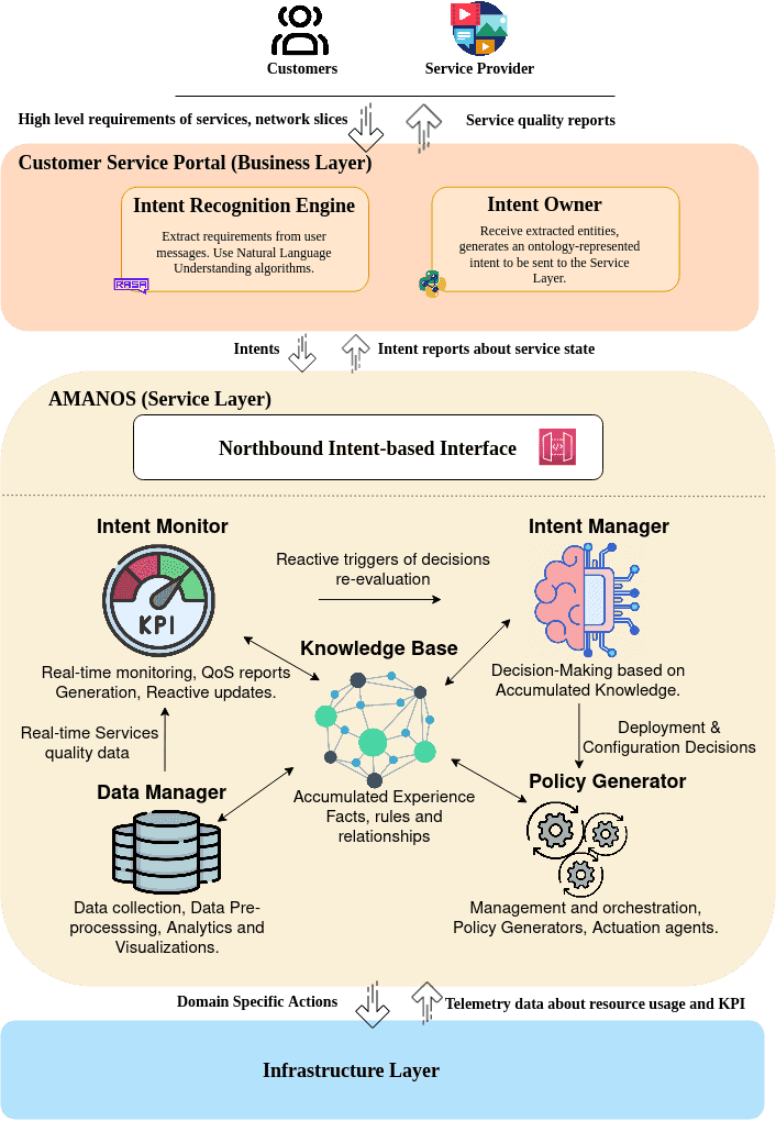
Intent-based networking is a key pillar in enabling next-generation autonomic networks. These networks are characterized by their ability to perform self-management, self-healing, and self-operation of resources while minimizing the interventions of human operators [1]. However, although these networks are designed to exhibit self-management properties, they still require input from an operator or outside system to provide operational guidance and information about the goals, purposes, and service instances that the network is to serve [1]. This input and operational guidance are commonly referred to as "intent", and a network that allows network operators to provide their input using intent is referred to as an "Intent-Based Network" [1]. Such a paradigm was the context of several research studies that proposed applications in different fields. This resulted in an important evolution in the definition of intent. The intent is defined by the IETF as "A set of operational goals (that a network should meet) and outcomes (that a network is supposed to deliver) defined in a declarative manner without specifying how to achieve or implement them" [1]. Alternatively, TM Forum proposed another definition which is considered as the latest definition, it describes an intent as "the formal specification of all expectations including requirements, goals, and constraints given to a technical system". An intent provides utilities, context, and requirements to the management system to take deci- sions that satisfy expectations. Figure 1 represents a comprehensive architecture composed of two main subsystems: The Customer Service Portal (CSP), which addresses the business layer of the mobile operator. The CSP is responsible for capturing the user’s high-level intent, understanding the expressed requirements, and translating them into a knowledge graph-based intent. The second subsystem is the Autonomous Management and Orchestration System (AMANOS), which operates at the service layer of the mobile operator. The AMANOS receives the service requests and generates the appropriate configuration to satisfy the expressed requirements and expectations.

Figure 1: Intent-Driven SCORING architecture.
Demonstration Scenario
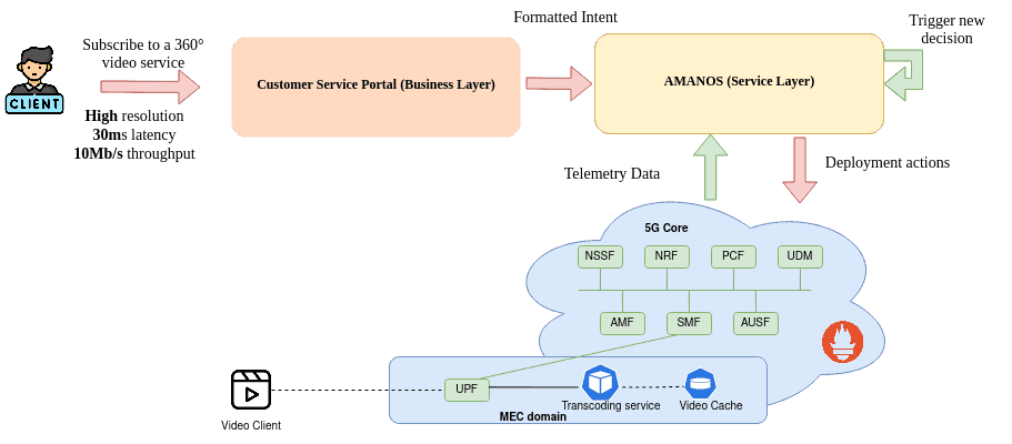
The demonstration scenario is depicted in Figure 2. The workflow commences with a user interacting with the Customer Service Portal subsystem. The user specifies their service requirements, including the type of service and various quality parameters such as resolution, latency, and throughput. These requirements are articulated in natural language format by the user. Subsequently, the Intent Recognition Engine translates and extracts a set of entities from the user's natural language message. These entities form the foundation of the intent object graph, which is constructed by the Intent Owner. The intent object graph is then forwarded to the Autonomous Management and Orchestration System (AMANOS) for further processing of the customer's request. Upon receiving the intent, the Intent Manager generates the appropriate decisions to fulfill the intent. These decisions are subsequently passed to the Policy Generator component to generate the corresponding configurations. The orchestrators in the edge and Core domains then implement these configurations to deploy the transcoding service and the 5G core network functions. Concurrently, the deployed service is continuously monitored by the Data Manager component. This component provides aggregated views to the Intent Monitor, facilitating the validation of intent fulfillment. If the intent is not fulfilled, the Intent Monitor requests the intent manager to generate a new decision. Figure 2 provides a visual representation of the described workflow and the various components involved in the demonstration scenario.

Figure 2: A 360° video streaming demonstration scenario.
Physical Test-Bed
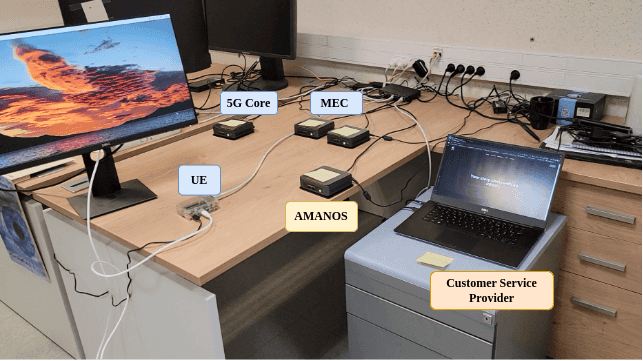
To evaluate the effectiveness of our proposed framework, we have designed an experiment environment as depicted in Figure 3. The platform is composed of the following components:
- The Customer Service Portal is deployed in a personal computer using docker-compose. The personal computer is characterized by an Intel i7-8750h processor and 19630 Mib of memory, a configuration very sufficient for such a subsystem.
- The Autonomous Management and Orchestration System (AMANOS) is deployed using Docker-Compose in an Intel NUC NUC7I5DNKE. The model is equipped with an Intel i5-7300U (2) 3.5 GHz and a 16 GB of memory.
- Network Infrastructure:
- Multi Access Edge Computing domain composed by a set of Intel NUC NUC7I5DNKE forming a Kubernetes cluster to provision the MEC services.
- 5G Core domain which follows the same strategy as the MEC domain. It includes 5G core network functions such as AMF, UPF, SMF. Finally, for user access, a Raspberry PI 4 has been used, which is connected to the 5G network using a gnb simulator, as well as a UE simulator.

Figure 3: Experiment Environment
Demonstration
In the following video, we will present the results of our experimentation regarding testing our system in an experimental test lab. We will cover all the steps we experienced during this phase.
References
[1] Alexander Clemm et al. Intent-Based Networking - Concepts and Definitions. RFC 9315. Oct. 2022. DOI: 10.17487/RFC9315.